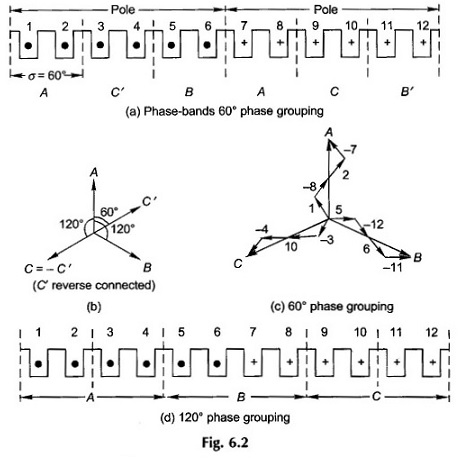
10 hp 36 slot 1440 rpm motor winding connection with diagram full video youtube channel link👇 … Each coil or winding represents a separate component of the motor and is connected in a specific manner to generate motion. In order to carry out the experimental test, the winding diagram in fig. · follow more courses at: A dc motor winding diagram typically consists of a series of parallel lines with numbers or letters indicating the different coils or windings. · here we see a winding diagram for a 3-phase ac induction motor or brushless pm motor (ipm), having 4 poles and 36 slots. It provides internal connection diagrams for three-phase windings. It can be used with either concentric or lap windings. Understand the different parts of the winding diagram and their roles in producing rotational motion in the motor. Explore the construction and working principles of the 3-phase induction motor winding diagram. Figure i-e represents a (4) phase motor with (12) slots and a (2) slot coil winding pitch. This winding could in fact be used with any ac machine, including a synchronous reluctance motor or a wound-field synchronous motor or generator. · we will apply red-colored wires to the running winding wires, and we will install black wires to the starting winding wires. 3 was applied to a 4-kw, 4-pole, 112-frame, squirrel-cage induction motor. Each of these components is connected to the circuit and has specific functions that allow the motor to run. Figure i-e is a (3) phase motor with (18) … The cooler motor will be rewind at a single speed only, as the exhaust fan does not need to remove the speed, so you rewind the exhaust fan at a single speed. This edition of easa internal connection diagrams contains significantly more connections and winding diagrams than the previous version (1982), as well as improved templates for drawing connection diagrams. Learn the basics of induction motor winding diagram, including different types of windings and their purposes in motor operation. This document contains technical specifications for an electric motor including its nameplate data, core dimensions, slot … · the basic components of a motor winding circuit diagram include: The stator, the armature, the rotor, the field windings, and the commutator. Explore the importance of this winding diagram for motor performance and efficiency. · 10 hp 36 slot motor winding and connection with diagram|three phase motor winding|motor winding Learn about the 3-phase induction motor winding diagram and how it functions. Learn about the 36 slot 4 pole double layer winding diagram, including its structure and how it is used in electrical machines.
Get Professional Results With This Easy 36 Slot Motor Winding Diagram
10 hp 36 slot 1440 rpm motor winding connection with diagram full video youtube channel link👇 … Each coil or winding represents a separate component...


