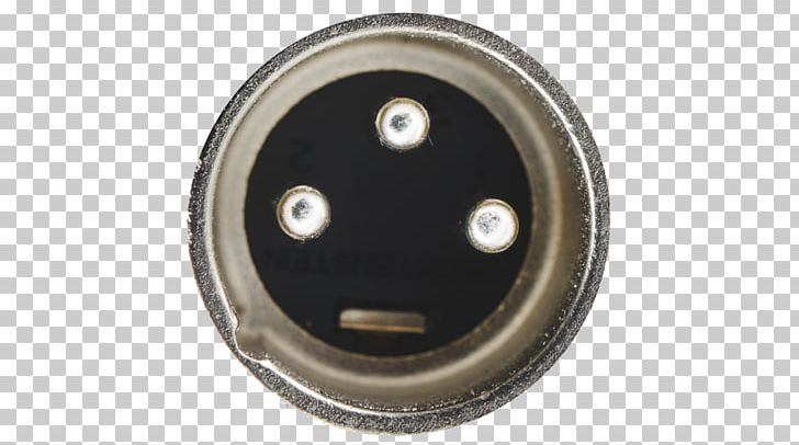
· for this connector model, we have the pinout in figure 3 below. · it is doable, simply wire the cable to the connectors on the plug. You will however need a xlr turnaround adaptor or custom xlrm … There are 7 contact pins, each of which is shown with its initials, both for the trs p10 input, 3 pins, and for the xlr canon input, 4 pins. Probably not necessary, but easier to solder since its one wire per solder cup, and you can pre-solder the jumpers before you mount the connector and make the final terminations. · learn how to read and follow neutrik xlr wiring diagrams to make perfect audio connections. · the solution is to use balanced cables with female xlr connectors at the source end and trs connectors at the amplifiers combo input end. This makes for a tight, reliable fit and … · i need to use the trs returns to give audio to 2 front of house speakers and 2 monitors. This guide explains xlr pin layouts, color codes, and step-by-step soldering instructions for neutrik connectors. · since there is no male connector that allows contact to both the trs and xlr connections simultaneously, its not easy to extend a combo input jack. · this would disconnect the xlr pins when a trs was inserted. I built a patch bay, using the neutrik … This is puzzling me! · the next studio wiring installation video will go over installing the snakes onto the panel, shielding and heat-shrinking, and completing the jumper connections on the back of the combo jack. · you need to be aware of the variance in shape of the tip of a trs or ts plug. You will be able to plug a trs cable straight in. We begin by understanding the type of connection we will be making. Rme use a standard neutrik combo component (afaik), so using cables with neutrik plugs should avoid … My monitors and front of house speakers are all powered speakers that have combo … I wonder if anyone can give me some advice on wiring for neutrik combo (trs / xlr) connectors please?
Neutrik Combo Xlr Trs Wiring Dont Get Fooled The Truth
· for this connector model, we have the pinout in figure 3 below. · it is doable, simply wire the cable to the connectors on...


